Intuitive System & Interface
Rapid Delivery
Fully Standards-Compliant
Turnkey Testing Packages
High ROI, Low Operation Costs
Reliable Support & Calibration
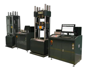
Servo Hydraulic Universal Testing Machine 2000kN
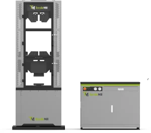
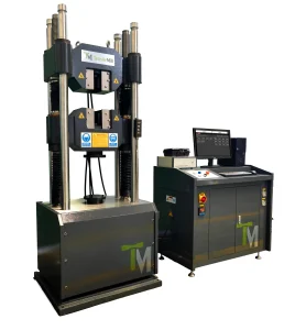
Servo-Hydraulic Universal Testing Machine (300 kN – 3000 kN)
The TM-SHM Series A Servo-Hydraulic Universal Testing Machine is a high-capacity system engineered for static tensile and compression testing of metallic materials under ASTM and ISO standards. Its dual-zone hydraulic load frame enables efficient tension–compression workflows without fixture changeover for QA laboratories and industrial testing environments. A rigid multi-column structure, high-resolution force measurement, and closed-loop servo control deliver stable and accurate performance across the 300–3000 kN range. Powered by GenTest software, the system supports standards-based test execution, real-time data analysis, and complete reporting for metal testing applications.
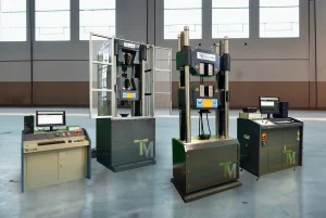
Electro Mechanical Universal Testing System 50kN / 1000kN with Precision Load Cell
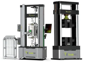
Electro Mechanical Universal Testing System 50kN / 1000kN with Precision Load Cell
The TM-EML Dual Column Floor Standing Universal Testing System provides high accuracy with a tolerance of ±0.5% of the reading value. Its wide testing range spans from 50kN to 1000kN (11,240lbf to 224,800lbf), catering to virtually all metal testing requirements. These units can also be fitted with a sub cell for enhanced precision in lower capacity testing. Additionally, the system offers a comprehensive array of testing capabilities including tensile, compression, bending, shearing, and more, along with compatible extensometer solutions for comprehensive material analysis.
Dual-Column Benchtop & Floor-Standing Universal Testing System 5 kN / 50 kN with Precision Servo Control
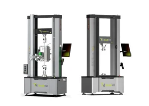
Dual-Column Benchtop & Floor-Standing Universal Testing System 5 kN / 50 kN with Precision Servo Control
The TM-EML Series C Dual-Column Benchtop and Floor-Standing Universal Testing System is an advanced electromechanical solution engineered for precise and stable material testing in laboratory and industrial environments. Covering a force range from 5 kN to 50 kN (1124 lbf to 11,240 lbf), it combines a servo direct-drive system, FEA-optimized frame, and high-rigidity structure to deliver Class 0.5 accuracy with smooth, vibration-free crosshead motion. This versatile system supports tensile, compression, flexural, and cyclic testing for metals, polymers, rubbers, foams, and composites. With dual configuration options (benchtop or floor-standing) and extended-travel models, the Series C adapts to a wide range of applications—from R&D to production quality control—while offering intuitive GenTest™ software and modular accessory compatibility for streamlined, high-precision testing.
Dual-Column Benchtop Universal Testing Machine 100 N / 10 kN with Precision Servo Control
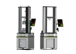
Dual-Column Benchtop Universal Testing Machine 100 N / 10 kN with Precision Servo Control
The TM-EML Series B Dual-Column Benchtop Universal Testing Machine delivers exceptional rigidity and precision for low-to-medium-force material testing. Designed for laboratories, universities, and production environments, it provides an accurate force range from 100 N to 10 kN (22 lbf to 2248 lbf) with ISO 7500-1 Class 0.5 accuracy. Its FEM-optimized dual-column frame and servo direct-drive system ensure smooth, vibration-free crosshead motion and perfect axial alignment for reliable tensile, compression, and flexural testing. Ideal for polymers, metals, foams, composites, and advanced materials, the Series B combines compact design with high stiffness, dual-channel safety logic, and advanced GenTest™ software for easy setup, real-time visualization, and automated data analysis—making it the benchmark solution for precision benchtop testing.
Single-Column Benchtop Universal Testing Machine 50 N / 5 kN with Precision Servo Control
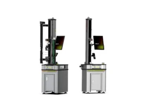
Single-Column Benchtop Universal Testing Machine 50 N / 5 kN with Precision Servo Control
The TM-EML Series A Single-Column Benchtop Universal Testing Machine is a compact yet high-performance electromechanical system designed for precision testing of low-force materials. Covering a force range from 50 N to 5 kN (11 lbf to 1124 lbf), it provides exceptional accuracy meeting ISO 7500-1 Class 0.5 standards. The system’s rigid single-column frame, pre-loaded ball screws, and direct-drive servo motor deliver smooth, vibration-free motion and stable control at speeds up to 2400 mm/min. Ideal for laboratories, research centers, and quality-control environments, it enables reliable tensile, compression, and flexural testing of plastics, rubbers, films, foams, composites, wires, adhesives, and other lightweight materials. Integrated GenTest™ software and modular accessory compatibility ensure intuitive operation and full compliance with ASTM and ISO standards.
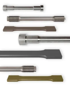
Grips and Fixtures for TensileMill Universal Testing Machines
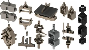
Grips and Fixtures for TensileMill Universal Testing Machines
Grips and fixtures are critical accessories for TensileMill Universal Testing Machines, ensuring accurate specimen holding and reliable load transfer during tensile, compression, flexural, shear, and puncture tests. Each configuration is designed to maintain specimen geometry, minimize slippage, and comply with ASTM, ISO, and other international standards. TensileMill CNC offers a complete range of grips and fixtures tailored to different materials and test methods — from wedge and pneumatic grips for metals and composites to self-tightening, eccentric roller, and bending fixtures for flexible, elastic, and brittle specimens. These precision-engineered components enable consistent, repeatable testing performance across research, quality control, and production environments.
Precision Alignment Device (NADCAP-Ready Precision Fixture)
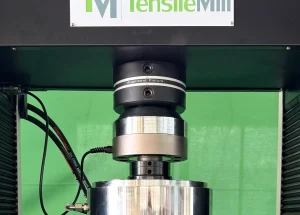
Precision Alignment Device (NADCAP-Ready Precision Fixture)
The Precision Alignment Device is a critical upgrade for any universal testing machine, designed to ensure perfect coaxial alignment and eliminate bending stress during material testing. Compatible with TensileMill CNC and third-party frames like Instron®, this NADCAP-ready fixture fine-tunes alignment to within ≤5% misalignment, boosting accuracy and repeatability. Equipped with a high-precision coaxiality meter, the device supports fast, in-house alignment verification per ASTM E1012 and NASM 1312B standards. Ideal for tensile, compression, and flexural testing, it enables labs to meet strict compliance standards while improving operator efficiency and test result reliability.
What It Takes to Do the Perfect Tensile Test
TensileMill CNC Inc. is well known for manufacturing top-tier tensile specimen preparation machines, we take pride in also offering cutting-edge tensile testing equipment that complies with the latest international standards. We achieve this by partnering with leading manufacturers of tensile testing equipment in the United States and around the globe.
 One Stop-Shop for Universal Testing Needs
 North American Quality
 Full Scope of Grips, Fixtures and Consumables
 User-Friendly
 Turnkey Solution Force Capacity Ranges from 1kN to 3000kN
We handpick our established and reputable partners based on their reflection with our philosophies. The company’s values include the ultimate customer experience, a user-friendly, efficient, cost-effective solution, and superior after-sales technical support to stay on top of your projects. With hands-on experience in sample preparation methods and materials testing, we combine years of field experience with industry best practices. As a result, we can match end-users with quality tensile testing equipment based on their needs.
You can submit your specifications through the form below for us to compile an individualized list of Universal Testing Machines. This will take into account your needs, budget, and any other preferences you may have.
How Do I Select the Perfect Tensile Tester?
Tensile testing machines must be selected based on several factors. If you are upgrading quality and functionality, or have decided to move materials testing in-house, you want to make sure that you are not buying a machine that won’t meet your requirements. As a rule, you will be guided by the type of testing you will perform – tensile, compression, fatigue, etc. – as well as the ASTM or ISO standards for the market you will enter. Among other factors to consider when selecting the perfect tensile tester are:
Optimal Performance Speed – Analyze the machine’s capabilities by examining specifications like motor speed, actuator efficiency, and drive horsepower to achieve top system performance.
Essential Load Capacity – Determine the necessary machine size based on your material testing load requirements. Depending on your maximum load requirements and whether hydraulic or electromechanical power is best for you, you can choose compact tabletop models or robust floor models.
Precise Test Calculations – It is very important to choose a tester with an appropriate control system. If complex calculations and a comprehensive standards library are required, PC-based software may be necessary, or a simple stand-alone digital controller may suffice.
Versatile Grips and Fixtures – Choose the right grips and fixtures for your samples, whether pneumatics, manuals, or specialized for rope and thread, to match your industry’s needs. It may be necessary to create custom fixtures for samples with unusual shapes and sizes.
TensileMill CNC Inc. works with top-tier manufacturers of tensile testing equipment in North America and Europe, allowing you to choose from a wide selection of applications using a simple online form.
Additional Considerations When Choosing The Right Tensile Tester
There are many different types of tensile testers, each with a unique feature. The right tool for your tensile testing equals a reliable manufacturer. Choosing a reliable manufacturer is the same as choosing the best tools. Ask these key questions when choosing a manufacturer for your tensile testing needs:
- Is the company established and has a good reputation?
- Can I contact organizations who currently have their equipment ?
- Is the company quick in replying to service and support inquiries?
- Where are the machines manufactured?
- Are the spare parts readily available and easily replaceable?
- What maintenance measures does the machine require?
- What is the expected life expectancy of the machine?
Our goal is to match all your requirements with an ideal manufacturer, guaranteeing that those criteria are met. You can let us know what you need by filling out the form below. By taking this step, you will be able to make an informed decision with confidence.
How Do I Prepare the Perfect Tensile Specimen?
In the past, manufacturers had to send their raw specimen batches of material to a specialist testing facility for the preparation of material property data. Materials would then be milled to create tensile specimens, which would be tested on a tensile tester to determine the properties of the materials.
Recently, manufacturing facilities have recognized the value of bringing testing equipment in-house to save time and money. Furthermore, they gain control over what passes a quality material standard, what testing method is most efficient, and under what conditions the most reliable data can be obtained. This process also saves weeks, quickly justifying the initial investment.
You can now prepare the highest-quality tensile specimen with only a few button pushes by investing in an affordable, industrial-grade tensile sample preparation machine. Whenever there is a high test volume or you want more control over the preparation of test samples, there are manufacturers who provide tensile specimen preparation equipment you can use in-house. As a manufacturer and distributor of both flat and round specimen preparation machines, TensileMill CNC Inc. is a prominent example of quality tensile specimen preparation equipment.
Our tensile specimen preparation equipment meets ASTM, ISO, DIN, JIS, and more standards for virtually all types of materials and has superior ease of use, accuracy, and efficiency. With intuitive software, even engineers with little experience can operate these machines easily. You will greatly benefit from learning more about TensileMill CNC’s tensile sample preparation equipment if you are involved in testing, manufacturing, or production.
How Do I Perform the Perfect Tensile Test?
Tensile Testing will expose the sample to a controlled amount of tension until failure occurs. During this test, other material properties can also be determined to guide design or production teams in making product or component improvements. Measurements of direct properties such as breaking strength, reduction in area, maximum elogation, and the ultimate tensile strength of the material can be used to determine other analytic properties through engineering calculations.
The tensile specimen is prepared depending on the test method or equipment being used and the specifications governing the type of material being tested. Usually a sample cross-section will feature a specimen with large, grippable shoulders and a gage section between the shoulders. The smaller gage section is where the controlled deformation and failure test is performed.
The specimens are prepared with either a square or round gage cross-section. The shoulder areas must be ample enough to permit a firm grip by the testing fixture. This gage length may vary depending on the standard specs being followed or the country ISO standards being used – and will also change in relation to the specimen diameter or cross-sectional area. The most common tensile testing guidelines can be found in ASTM D638.
We encourage you to fill out the form below to be connected with the optimal manufacturer of Tensile Testing should you need any further help or in-person assistance.
GET A QUOTE

Contact TensileMill CNC Inc. to learn more about how easy preparing and testing tensile specimen in-house can be. When you partner with the right companies with the right equipment, your tensile testing procedures will become hassle free, cost-effective, and provide an accurate method for preparing and testing your tensile specimens.
What service and technical support do you provide for Flat Tensile Sample Preparation machines?
Will burrs remain on tensile specimens after the cutting cycle on a TensileMill CNC sample preparation system?
Edge condition after machining depends on material type, cutter or insert condition, feed and speed, coolant, and toolpath strategy. With the supplied starter tooling and tuned parameters, burr can typically be minimized to a negligible edge or eliminated. Good practices include matching the cutter or insert grade to the alloy, keeping cutting edges sharp, using adequate coolant, and programming climb milling with a light finishing pass of about 0.005 to 0.010 in (0.13 to 0.25 mm) stock. Adding a small edge break of roughly 0.005 in (0.13 mm) with a chamfer or deburr pass helps reduce handling nicks before testing. If some burr remains, quick secondary methods are common in tensile labs: hand files, deburring blades, small countersinks, tube deburring tools for round gage sections, fine flap wheels, and nonwoven abrasive pads. Remove only the raised edge so gage width or diameter is not altered, then verify dimensions and surface quality prior to testing. Our team can recommend tooling and parameters for both flat and round workflows to help you hit your required finish with minimal rework. If you would like to source deburring media, end mills, inserts, and related supplies, you can review options on the Consumables and Spare Parts page.
What tensile specimen geometries and dimensions can TensileSoft prepare?
TensileSoft supports both standard straight-edge and tapered-edge flat tensile specimens. Operators can select common dog-bone geometries from ISO 527 and ASTM D638 or input custom sizes. On compact systems such as the TensileMill CNC MINI, tapered-edge profiles are typically produced up to 0.50 in (12.7 mm) thickness. In practice, you choose a template or define gauge length, grip width, fillet radius, overall length, and thickness, then clamp the blanks and start the cycle. The software creates the profile and edge transitions, applies optimized toolpaths, and accommodates single-part or stacked cutting to increase throughput. Final size ranges depend on machine travel, fixturing, material, and cutter selection, so your achievable envelope is governed by the specific flat specimen system installed. The same workflow applies across the MICRO, MINI, Classic Upgrade, and XL flat machines, giving plastics and metals labs a fast path to repeatable edges for standard-compliant tensile testing. If you would like to compare flat-specimen systems and software workflows, you may review details on the Flat Specimen Preparation Equipment Lineup page.
How Many Flat Tensile Specimens Can I Prepare Per Cycle?
Throughput per cycle depends on the machine configuration, workholding, blank size, and material hardness. Standard flat-specimen setups typically machine one coupon at a time, while optional multi-station and triple-clamp fixtures allow multiple blanks or stacked sets in a single program. On compact systems, a single-station clamp is common for one-part cycles. Larger or upgraded setups can use multi-station fixtures. With a triple-clamp configuration, operators may load up to three stacked blanks, subject to total stack height, cutter reach, and part rigidity. As a practical reference, many labs run stacks totaling about 1.0 in (25.4 mm), and individual coupons up to 0.5 in (12.7 mm) thick on select models. The achievable part count also varies by alloy and starting thickness, since harder materials and wider gauge sections call for more conservative feeds and additional passes. If you share your material grade, starting thickness, and target geometry, our team can recommend a cycle plan and fixture package that balances part count, surface finish, and tool life. If you would like to discuss throughput and fixturing for your application, you can connect with our team on the Contact Us page.
Can I Stack Multiple Blanks for Faster Tensile Sample Preparation?
Yes. Our flat-specimen systems support stacked machining using a dedicated clamping device that accommodates a combined stack height up to 1.0 in (25.4 mm). The clamp grips the full pack so the mill can rough and finish several specimen profiles in one program with stable holding and repeatable alignment. Stacking is commonly used for metals and polymers to raise throughput while maintaining final geometry. Use uniform blank thickness, register the edges, and verify cutter reach across the full 1.0 in (25.4 mm) height. Apply toolpaths, feeds, and coolant suited to the material to manage heat and burr formation. After machining, separate the coupons, deburr, and measure according to the applicable standard, for example ASTM E8 for metallic flats or ISO 527 for plastics, so each specimen meets the required dimensions and radii. This approach reduces handling time per part without changing compliance, since every coupon is inspected individually. If your workflow calls for taller packs, unusual geometries, or abrasive alloys, specialty clamps and tooling packages are available to match your specimen design and production rate. If higher throughput is a priority, you may review model compatibility and fixturing details on the Flat Tensile Test Sample Preparation Machines page.
What Additional Maintenance Steps Extend the Life of a Tensile Sample Preparation Machine?
Routine preventive maintenance and a clean workspace go a long way. Keep the lubrication reservoir topped with the recommended oil, wipe down exposed surfaces, and remove chips after each shift to reduce wear on moving components and guarding. For daily care, vacuum chips instead of blowing them into seals, clear the chip tray, and dry any coolant residue on the table, vises, and fixtures. Confirm that the automatic lubrication system is cycling and that lines are intact. Inspect the spindle taper and tool holders for debris, then lightly clean and re-seat them to protect runout. Keep the coolant or mist system clean by using approved fluids and replacing filters as needed. Periodically check way covers, door interlocks, cable carriers, and the condition of belts, fasteners, and guarding. Verify that the air supply is clean and dry to protect valves and actuators. Back up machine parameters and software, and record service actions in a simple log so you can spot trends. Train operators to run a brief warmup program at start of day, handle specimens and tooling carefully, and report any unusual noise, heat, or vibration immediately. If you would like maintenance guidance tailored to your setup or a recommended service interval, you can connect with our team on the Contact Us page.
How Many Tensile Specimens Can Be Prepared Per Cycle?
Throughput per cycle varies by material, specimen geometry, and workholding. On flat CNC tensile systems, you can machine a single coupon in one setup or run a batch using multi-station clamps, fixture plates with nesting, or stacked blanks when thickness and rigidity allow. The achievable count depends on thickness and hardness, which influence cutter engagement, pass strategy, and allowable stack height. Standards such as ASTM E8 or ISO 6892 define gauge length and width, which dictate part spacing and fixture pocket layout. Tough alloys and thicker stock increase cycle time and often favor one-up machining with separate rough and finish passes, while thinner sheet and softer metals suit nested batches that deliver higher parts per hour. Tool diameter, corner radii, coolant delivery, and changeover method also affect real-world yield. If you share your alloy, initial blank size, thickness, and target standard, our team can provide an application-specific parts-per-cycle and hourly throughput estimate. If you would like to compare batch fixturing and table sizes, you can review models and options on the Flat Tensile Test Sample Preparation Machines page to learn more about throughput planning.
What Types of Base Fixtures Are Available for Tensile Sample Preparation Machines?
Flat tensile preparation systems from TensileMill CNC are supplied with a stainless steel base fixture tailored to the specimen geometry in your method library. Optional clamping fixtures expand the holding envelope for different blank lengths, covering approximately 15 in down to 4 in (381 mm to 102 mm). Each package also includes an ER collet and carbide end mills, with only the cutters considered routine consumables. The base fixture is built for long service life and resists wear in high-throughput labs. It is configured to support common flat specimen profiles used in standards such as ASTM E8 for metals, ISO 6892-1, and ASTM D638 for plastics when applicable to your workflow. When your starting blank length changes, selecting the matching clamping fixture maintains full contact and stable clamping, which helps hold gauge-width tolerance and finish quality during milling. End mill life ranges from weeks to months based on part volume, material hardness, and blank thickness, so keeping a small stock of our coated carbide tools helps prevent unplanned downtime. If you would like to compare fixture options or check current availability, you can review details on the Tensile Sample Preparation Consumables, Fixtures, and Spare Parts page.
What Is the Typical Lifespan of End Mills for TensileMill CNC Milling Machines?
Tool life varies because it depends on material hardness, blank thickness, toolpath strategy, coolant use, and spindle setup. Our systems ship with specialty carbide end mills in bright finish or Alcrona Pro coating that are engineered for tensile specimen machining. In production labs, these cutters commonly deliver extended service across multiple batches, including high-throughput programs, but there is no single hours-or-parts figure that applies to every application. For the longest life, match the geometry and coating to the workpiece: bright finish for aluminum and other nonferrous materials, AlCrN-type coatings such as Alcrona Pro for steels, stainless, and nickel alloys. Use conservative radial engagement, climb milling on profiles, ample coolant, and rigid fixturing. Keep spindle runout at or below 0.001 in (0.025 mm). Replace a cutter when surface finish begins to dull, burrs increase, spindle load trends upward, or edge wear and micro-chipping become visible under magnification. Keeping a spare set of identical tools on hand helps maintain consistent specimen quality and uptime. If you would like application-specific tooling guidance or to review stocked options, you may explore the Consumables and Spare Parts page for end mills matched to our sample preparation machines.
How Do Flat Tensile Specimen Machines Keep the Gauge Section Centered During Two-Sided Machining?
Symmetry is achieved with a one-setup flip process that keeps the blank registered to the same clamping faces for both passes. The machine completes the first side, pauses, and the operator rotates the fixture while the work offset and datums remain unchanged. The second operation runs a mirrored toolpath around the same centerline, so the gauge section stays centered and thickness remains uniform. Dedicated reference surfaces in the fixture control X and Y location, while the clamping stack maintains Z datum, preventing drift that commonly appears when parts are reindicated on manual equipment. Matching step-downs, cutter paths, and feed strategies for both sides keep cutting forces balanced, which helps avoid taper, bow, or offset shoulders. The same workflow applies to multi-part fixtures or stacked blanks, so every coupon in the set carries the same geometry. For labs preparing flat specimens to ASTM E8 or ISO 6892, this approach supports gauge section alignment and parallelism requirements without extra setup time. If you would like to compare fixturing and workflow options, you can review model details on the Flat Specimen Preparation Equipment Lineup page.
What Does the Flip-Jig Fixture Do in Two-Sided Tensile Specimen Machining?
The flip-jig is a dedicated workholding fixture that clamps the specimen blank for two-sided milling, keeps the centerline aligned, and preserves the work offset during rotation. By holding the blank in a consistent datum, it allows the part to be rotated when prompted by the software without changing the machining origin. In practice, you clamp the raw blank, machine the first side, then rotate the part 180 degrees within the same fixture when the program prompts a flip. Because the datum remains constant, the controller continues from the same zero, which reduces thickness mismatch, shoulder radius offset, and gauge-section runout compared with manually re-centering on a general-purpose CNC. The result is tighter correlation between faces, faster changeovers, and stable parallelism across batches. One flip-jig is supplied with the system and is selected to match expected specimen length. Available sizes include 4 in (101.6 mm), 8 in (203.2 mm), and 12 in (304.8 mm). Selecting the correct size matches the clamping span to the blank, improving stability and surface finish on thin or long samples. If you would like to compare compatible systems and fixturing options, you can review details on the Flat Tensile Test Sample Preparation Machines page.
How Many Steps Are Required to Prepare One Flat Tensile Specimen on a TensileMill CNC?
Most users complete one flat tensile specimen in five steps. Select the standard or custom profile on the touchscreen, clamp the blank in the flip fixture against the alignment stop, start the first-side program, rotate the flip fixture when prompted without re-centering, then resume the cycle to machine the second side. The built-in library covers common profiles such as ASTM E8 or ISO 527, so dimensions are loaded once and stored for repeat runs. Toolpaths, spindle speed, and motion control are automated, which keeps operator involvement to alignment and the single flip. The fixture datum preserves registration between sides, producing consistent gage width and surface finish for reliable tensile results across batches. If you would like to compare model options for flat specimen machining, you can review capabilities on the Flat Specimen Preparation Equipment Lineup page.
How Is the Flood Coolant System Maintained and Refilled?
Our flat-specimen machining systems use a recirculating flood coolant housed in the machine base, so all plumbing, filtration, and return flow stay inside the enclosure. Routine care focuses on fluid level, concentration, and chip control to keep cut quality and pump life stable in a lab setting. To refill, open the sump access inside the enclosure and add premixed water-soluble coolant until the sight gauge or fill mark is reached. Typical lab units hold about 10 gal (37.9 L). After filling, run the pump briefly to verify steady return flow to the tank. For day-to-day operation, top off with the same premix rather than straight water to avoid diluting the blend. Maintenance includes checking concentration with a refractometer and adjusting with concentrate or water per the coolant manufacturer’s chart, cleaning the intake screen and return tray so chips do not starve the pump, and skimming tramp oil as needed. Plan full tank cleanouts on a usage-based interval, for example every few months, which includes draining, wiping sediment, flushing lines, and replacing disposable filters if fitted. No external coolant supply is required, which keeps service simple for laboratories and small production cells. If you would like a model-by-model look at coolant features for our flat specimen mills, you can review details on the Flat Tensile Test Sample Preparation Machines page.
Is In-House Tensile Specimen Preparation More Cost-Effective Than Outsourcing?
For labs with steady testing, in-house preparation typically reduces total cost after the initial equipment purchase, because the marginal cost per specimen becomes far lower than paying per batch externally. For occasional or sporadic testing, outsourcing can be practical since there is no upfront capital spend. Outsourcing carries variable charges that repeat with every order: setup and machining fees, packaging, two-way shipping, potential rush charges, and idle time while parts are in transit. Those costs scale directly with demand and can rise with tighter tolerances or special profiles for standards such as ASTM E8 or ISO 527. If rework is needed, the cycle repeats. In-house shifts spending to a fixed asset plus predictable items like cutters, inserts, coolant, and routine maintenance, along with operator time. Once a flat or round specimen system is installed, the next sample mainly reflects tool wear and minutes of machine time, and adjustments happen immediately without courier delays. Facilities running regular production checks, R&D iterations, or academic coursework usually see per-specimen cost drop as throughput increases, especially when using batch cycles or multi-part fixtures to machine multiple blanks in one run. If you would like to discuss throughput, staffing, and payback for your lab, you can connect with our team on the Contact Us page.
How Do I Choose Between Flat and Round Tensile Specimen Preparation Systems?
Start with your material form and the target geometry required by your test method. Flat preparation is ideal for sheet, plate, or molded panels, commonly used for ASTM E8 metals or ISO 527 plastics. Typical flat dog-bone sizes include 0.25 to 1.00 in (6 to 25 mm) gauge width with 1.00 to 2.00 in (25 to 50 mm) gauge length and 0.125 in (3.2 mm) fillet radii. Round preparation suits bar, rod, wire, or cast buttons, with frequent sizes of 0.250 to 0.500 in (6 to 13 mm) diameter and 2.00 to 4.00 in (50 to 100 mm) gauge length. Target tolerances often hold ±0.001 in (±0.025 mm) in the gauge section and 0.001 in TIR (0.025 mm) concentricity for round specimens. Consider throughput and handling. For high coupon volumes across multiple alloys, a fixtured flat CNC system supports repeatable nesting and quick changeovers. For rounds, a programmable lathe-style machine with tailstock support and center drilling maintains straightness on longer pieces, for example 6 to 12 in (152 to 305 mm) overall length, while flood or mist coolant protects both metals and polymers. Confirm UTM and grip compatibility early. Flats pair well with wedge or pneumatic grips using 1 to 2 in (25 to 50 mm) jaw widths. Rounds may require collets, shoulders, or threaded ends such as 0.500-20 UNF, with shoulder perpendicularity within 0.002 in (0.05 mm). Surface finish affects results, so polish the gauge section longitudinally to Ra ≤ 32 µin (0.8 µm), or to 16 µin (0.4 µm) for notch-sensitive materials, and verify dimensions against the selected standard during first-article inspection. If you are comparing flat and round preparation solutions, you can explore the TensileMill CNC Homepage to review product families on the page.
How Do I Choose Between Flat and Round Tensile Specimen Preparation Systems?
Selection depends on your product form, the governing standard, and downstream gripping. For sheet, plate, and extrusions, a milling-based system produces flat coupons to ASTM E8/E8M or ISO 6892-1 for metals, and ASTM D638 or ISO 527 for polymers. For bar, rod, and forged stock, a lathe-style system machines round specimens, typically 0.500 in (12.5 mm) nominal diameter with 2.00 in (50 mm) gauge length for ASTM E8, or subsize options when thickness limits the section. Consider precision and finish. Flat machining supports tight edge tolerance around ±0.001 in (±0.025 mm) and surface finish near 32 µin Ra (0.8 µm) when tooling is sharp. Turning round specimens makes concentricity and straightness easier to control, often within 0.001 in (0.025 mm) TIR, which reduces bending errors. If your lab needs a mirror finish for strain extensometers, plan on a polishing pass to achieve 16 µin Ra (0.4 µm) or better. Throughput and fixturing also matter. Flat systems can fixture multiple blanks per cycle, which is efficient for sheet from 0.020 to 0.250 in (0.5 to 6.0 mm) thickness. Round systems suit continuous runs from 0.125 to 1.000 in (3.2 to 25.4 mm) diameter bar. Verify your UTM grip style, wedge grips for flat widths like 0.500 in (12.5 mm) or collet or threaded holders for round shoulders, and confirm overall length, for example 6.0 to 10.0 in (152 to 254 mm), matches the machine and standard. For additional guidance, you can connect with our team on the Contact Us page.
How Do I Choose the Right Flat Tensile Sample Preparation Machine for ASTM E8, ASTM D638, or ISO 527 Work?
Start with your material range and blank size. If most coupons come from sheet, a compact work envelope such as 12 in × 12 in (305 mm × 305 mm) is efficient. For plate cutting or multiple-up nesting, consider larger travels, for example 24 in × 36 in (610 mm × 914 mm). Match spindle power and tooling to your thickness, such as 0.020 in to 1.50 in (0.5 mm to 38 mm), and plan for tool diameters from 0.0625 in to 0.375 in (1.6 mm to 9.5 mm). If you would like to compare sizes, options, and workflows side by side, you can review model details on the Flat Tensile Test Sample Preparation Machines page.
What Setup Steps Improve ASTM E8 Compliance In Automated CNC Tensile Specimen Preparation?
Start with workholding and alignment. Tram the fixture or vise so the jaw face runs within 0.0005 in (0.013 mm) over 4.0 in (102 mm). Probe the blank’s centerline for X–Y, then set Z with an automatic tool setter to ±0.0002 in (±0.005 mm). Use a dedicated coupon fixture or dowel-pinned soft jaws to keep the gauge section square to the spindle. Verify spindle warm-up and backlash compensation before the first article. Program a two-stage strategy. Rough, leaving 0.010 in (0.25 mm) per side. Finish with a climb pass along the gauge length using a 0.003 in (0.08 mm) radial step at 12–20 ipm (305–508 mm/min) and 0.10–0.20 in (2.5–5.0 mm) axial depth, adjusted to material hardness. Maintain coolant flow near 0.5–1.0 gal/min (1.9–3.8 L/min) to limit heat that can distort width. Blend shoulder radii to the print, and break edges lightly to avoid burrs that affect gauge length marking. Close the loop with metrology. Many labs hold gauge width to ±0.001 in (±0.025 mm) for process control, parallelism within 0.0008 in (0.020 mm), and surface roughness near Ra 32–63 µin (0.8–1.6 µm). Mark a 2.0 in (50 mm) gauge length for common subsize per ASTM E8, record tool wear, and replace small end mills once width drift exceeds 0.0005 in (0.013 mm) or after 25–35 coupons. If you would like to review fixtures, software options, and capacities, you can explore details on the Flat Tensile Test Sample Preparation Machines product page.
How Do CNC Settings and Finishing Steps Reduce Tensile Specimen Defects?
Defect control starts at the machine. Use a roughing pass, then a light finishing pass around the gauge with climb milling and sharp tooling. Keep the finish allowance small, about 0.005 to 0.010 in (0.13 to 0.25 mm). Feed gently through shoulders to avoid chatter marks. Maintain coolant near 0.5 to 1.0 gal/min (1.9 to 3.8 L/min) to limit heat and preserve microstructure. Replace tools before a visible wear land, around 0.004 in (0.10 mm), to reduce burrs and taper. Target a uniform surface. For metals, a finish of Ra ≤ 32 µin (0.8 µm) suits general tensile work; high-strength or fatigue-sensitive lots benefit from Ra ≤ 16 µin (0.4 µm). Break edges with a 0.010 to 0.015 in radius (0.25 to 0.38 mm) or a 45° × 0.010 in chamfer (0.25 mm) so edges do not act as stress raisers. Polish lengthwise with 600, 800, 1200 grit, then, if required, a 120 µin (3 µm) diamond compound. Avoid transverse scratches across the gauge. Verify geometry per the drawing and the applicable standard. Check width and thickness within ±0.001 in (±0.025 mm) where practical. Confirm gauge length and shoulder radii per ASTM E8 or ISO 6892-1 for metals, or ASTM D638 for plastics. A quick straightness check over 4 in (100 mm) helps prevent off-axis loading in the UTM. If you would like to review machine options for flat specimens, you can explore details on the Flat Tensile Test Sample Preparation Machines equipment page.
Which CNC Practices Reduce Machining Defects in Tensile Specimens?
Set the finishing strategy to limit stress risers. Use climb milling for the final pass with a light radial depth, about 0.005 in (0.13 mm), and a feed near 0.002 in/tooth (0.05 mm/tooth). Keep the tool sharp to prevent chatter. After machining, break edges with a light 0.010 to 0.020 in (0.25 to 0.50 mm) chamfer or radius, then deburr. Target burr height under 0.002 in (0.05 mm). Verify geometry before polishing. Measure width and thickness at three locations with a micrometer, and check grip parallelism within 0.001 in (0.025 mm) and gauge flatness within 0.002 in (0.05 mm). Conform dimensions to ASTM E8 or ISO 6892-1 for metals, and ASTM D638 or ISO 527 for plastics. Finish the gauge section to 32 to 63 µin Ra (0.8 to 1.6 µm) for routine tensile tests. For high strength or fatigue-sensitive alloys, refine to 16 µin Ra (0.4 µm) and keep scratch direction along the load axis. If heat tint or work hardening is suspected, follow with a light longitudinal polish to restore a uniform surface without changing section size. If you would like to review machining options for flat specimens, you can explore details on the Flat Tensile Test Sample Preparation Machines equipment page.
Our universal testing machines and tensile testers are designed for precise, repeatable mechanical testing across a wide range of materials. Built to meet ISO 6892 and ASTM E8 standards, our electromechanical and servo-hydraulic systems deliver reliable tensile and compression results in both laboratory and industrial environments. Whether you’re looking for a digital tensile tester, a dual-column system, or a fully automated material strength testing machine, we offer ISO-compliant solutions tailored to your application. Request a quote today for high-force, computerized tensile testing equipment trusted by engineers worldwide.