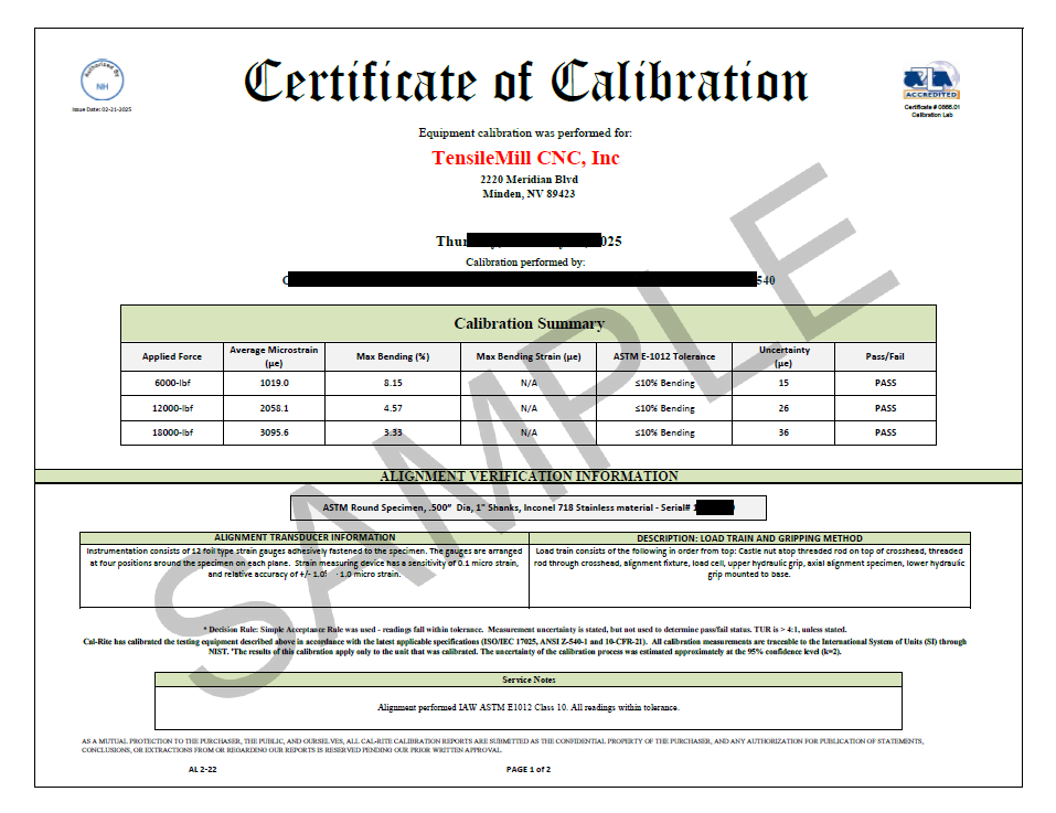
In material testing, particularly tensile testing, consistent and reliable results depend on calibrated equipment and well-defined procedures. TensileMill CNC collaborates with ISO 17025 accredited calibration labs to certify testing machines, load cells, extensometers and specimen preparation equipment according to recognized industry standards. Our certification support covers ASTM, ISO and related frameworks, including projects that require compliance for aerospace, automotive and general industrial applications.
Certification is performed using accepted technical protocols such as ASTM E4 and ISO 7500-1 for force verification, ASTM E1012 for frame alignment, ASTM E83 and ISO 9513 for extensometer calibration, as well as ASTM E8 and ISO 6892-1 for tensile testing of metals. These standards define the preparation of specimens, the loading rate used during testing and the format of recorded results. This allows data to be reproduced across different facilities and accepted by customers, auditors and regulatory bodies.
Beyond calibration and method-based testing, we also support accreditation under ISO/IEC 17025:2017. This framework outlines how laboratories manage quality systems, maintain measurement traceability, evaluate uncertainty and demonstrate technical competence, which is critical when certifying results for external review.
Whether you operate TensileMill CNC machines or equipment from another manufacturer, we coordinate the full certification process and provide traceable documentation through our accredited partners. If certification is required for an upcoming audit or project, you can submit a request and our team will guide you through the next steps.
ISO/IEC 17025:2017 Certification
TensileMill CNC works directly with ISO 17025 accredited calibration providers to help testing facilities meet ISO/IEC 17025:2017 requirements. The standard outlines how a laboratory must demonstrate technical capability, maintain measurement traceability, document uncertainty, and operate under a controlled quality system — all of which form the foundation for credible test results.
We coordinate ISO 17025-compliant calibration and certification for tensile testers, load cells, extensometers, and alignment verification equipment, regardless of whether the system was supplied by TensileMill CNC or another manufacturer. Clients receive calibration reports and documentation that meet the expectations of auditors, customers, and internal quality teams.
Our process follows the same accreditation scope used by ISO 17025 laboratories such as Cal-Rite, giving facilities access to valid, traceable certification packages for audits, equipment validation, or onboarding of new machines. If your facility is preparing for compliance, we can connect you with the appropriate accreditation pathway and manage the certification workflow on your behalf.

ASTM E4 / ISO 7500-1 Force-Measurement Certification
If you test force-measurement equipment and need certification according to ASTM E4 (Class A) or ISO 7500-1 (Class 0.5 or 1), we handle the full process — whether the system came from us or from a third-party supplier.
These standards set out how a testing machine’s force-measuring system must perform. For example, ISO 7500-1 defines calibration and verification of static uniaxial testing machines, specifying that calibration must cover the full operating range, and that the machine must meet the assigned accuracy class after a general inspection and force-proving verification.
ASTM E4 describes accepted procedures for verifying force-measuring systems in both tension and compression machines, requiring that indicated force values stay within ±1 % of the applied load across the verified range and that repeatability meets strict criteria.
Our certified process includes multi-point calibration: applying known reference forces at various levels (from low loads up to full capacity), checking the machine’s responsiveness in both increasing and decreasing load cycles, and assessing repeatability and reversibility. After calibration, we issue traceable documentation that records actual performance, error margins, and measurement uncertainty — documentation that auditors, customers, or regulatory bodies will accept without questions.
With this certification in place, universal testing machines, load frames, force sensors or load cells operated in metallurgical, aerospace, automotive or industrial labs produce data you can rely on. This minimizes risk of challenge or data rejection during contract reviews, quality audits or certification procedures.
Request certification to start: we coordinate with our ISO 17025-accredited partners, manage all logistics, and deliver a full compliance report with your equipment.

ASTM E1012 / ASTM E2309 / ASTM E2658 — Frame Alignment & Displacement-Verification Certification
If your lab needs to verify alignment or displacement-measurement systems for tensile, compression, or fatigue testing, we can help. We support calibration and certification not only for equipment supplied by TensileMill CNC, but also for third-party machines and accessories under these standards.
- ASTM E1012 deals with alignment verification of testing frames. It requires use of a strain-gauged alignment specimen to check if the applied load is truly axial — without unintended bending or eccentricity. This is particularly important when precision counts, as misalignment can skew tensile or compression results.
- ASTM E2309 governs calibration of displacement-measuring devices (such as cable-extension transducers or digital indicators) used in material testing machines, ensuring accurate displacement data during tests.
- ASTM E2658 covers verification of the machine’s speed or displacement-measuring system (when using cable-extension + time-based displacement), confirming that indicated displacement vs. actual matches within defined tolerances.
These checks — frame alignment, calibration of displacement sensors, displacement-vs-time verification — help labs maintain measurement integrity. With properly aligned frames and calibrated displacement systems, test results are more reliable, repeatable, and defensible during audits or third-party reviews.
We coordinate the full certification cycle via ISO-accredited partners: setup, calibration, verification, documentation. If you need to equip a lab or bring existing equipment into compliance, request certification and we’ll manage the process end to end.
UL Certification for U.S. Compliance and Equipment Approval
When tensile testing machines are installed in the United States, electrical and safety conformity is commonly evaluated according to UL standards. UL certification confirms that equipment has undergone independent safety review through an OSHA-recognized NRTL and is accepted by inspectors and facility engineers responsible for commissioning. This makes UL compliance an important step for laboratories, manufacturers, and research centers planning to operate tensile systems within U.S. regulatory environments.
TensileMill CNC can supply tensile testing machines and supporting equipment in UL-certified configurations upon request. Certification may include review of electrical architecture, wiring and grounding methods, operator safety controls, labeling, and panel design to confirm that the system meets UL requirements and aligns with local electrical codes. This helps reduce installation delays and streamlines approval during facility inspections and commissioning.
If your project specifications, customers, or internal quality policy require UL Listed or UL Recognized equipment, we can help initiate certification for both newly purchased machines and third-party systems already in use. Request certification to begin the UL approval process, or contact our team for guidance on U.S. compliance requirements for tensile testing equipment.
CSA-Certified Systems for the Canadian Testing Market
Operating a tensile testing facility in Canada typically requires equipment that is approved under CSA safety and electrical regulations. TensileMill CNC offers testing systems that can be supplied with CSA certification, verifying that the equipment has been reviewed and qualified through independent safety evaluation to meet Canadian compliance expectations. This leads to smoother installation, faster commissioning, and better acceptance during inspections or facility audits.
For Canadian clients, CSA certification is available for tensile testing machines, force measurement frames, extensometer-ready systems, electrical panels, and integrated safety controls. Customers who require documentation for internal validation or regulatory verification receive full certification paperwork alongside their machine, supporting readiness for quality reviews and audit conditions.
International laboratories with Canadian compliance requirements can also obtain CSA-certified equipment upon request, including certification for new systems or for existing third-party tensile machines that require approval before operation. Request certification to begin the process, or contact our team if you need support selecting the appropriate CSA compliance path.
NADCAP Accreditation for Aerospace and Defense Testing
NADCAP is an accreditation system for critical processes used in aerospace, defense, and related industries. The program is managed by the Performance Review Institute (PRI) with oversight from major OEMs, suppliers, and regulatory representatives. NADCAP accreditation is widely recognized across the global aerospace sector and is often required for participation in approved supply chains.
The program covers key special processes such as mechanical and materials testing, heat treatment, coatings, non-destructive examination, and other controlled procedures.
What NADCAP Accreditation Provides
NADCAP reduces audit workload by replacing multiple customer audits with one unified review. This cuts waiting time, frees staff, and lowers the cost of compliance.
Accreditation gives confidence to OEMs, contractors, and auditors. It shows that equipment, procedures, and personnel follow aerospace-level requirements.
Standardized quality procedures and controlled documentation help maintain stable test results, avoid nonconformities, and simplify future inspections.
In aerospace and defense programs NADCAP is often mandatory. Accredited suppliers receive access to contracts that are closed to non-approved facilities, strengthening their position in the supply chain.
How NADCAP Audit Works Step by Step
The accreditation process follows a structured sequence. Each stage confirms that equipment, procedures, documentation, and personnel meet aerospace-level quality expectations. Below is a simplified step-by-step overview of how a typical audit progresses:
Step 1: Registration and Application
Companies submit a request to PRI and select the scope of accreditation, such as Materials Testing Laboratory (MTL) or other special process categories.
Step 2: Audit Scheduling and Preparation
A qualified auditor is assigned, and the facility performs an internal readiness review. Documentation, calibration records, quality procedures, and traceability systems must be checked in advance.
Step 3: On-Site Audit
The auditor evaluates equipment setup, operator qualification, process control, documentation practices, calibration certificates, and quality-management execution.
Step 4: Corrective Actions if Required
Any non-conformance identified during the audit must be corrected and documented. Evidence of corrective action is reviewed before the process moves forward.
Step 5: Review and Certification Decision
A PRI task group reviews the audit report and issues a certification decision based on compliance level and submitted evidence.
Step 6: Ongoing Surveillance
Periodic follow-up audits and monitoring are required to keep accreditation active and demonstrate continuous adherence to NADCAP expectations.
Industries and Processes Recognized Under NADCAP
NADCAP applies to processes that require controlled testing, traceability and consistent results. The program is used in:
- materials and mechanical testing
- non-destructive examination
- heat treatment and coatings
- welding and fabrication work
- chemical processing and metallurgy
- additive and precision manufacturing
What NADCAP Certification Means for Suppliers
Accredited suppliers operate under standardized quality controls, maintain traceable calibration records and pass a single unified audit accepted across OEM chains. For many aerospace and defense contracts NADCAP approval is a requirement, not an option.
Accreditation reduces repeated customer audits, lowers internal compliance cost and improves acceptance of test data. It also provides access to programs closed to non-approved labs and strengthens supplier credibility during procurement evaluations.
Support for NADCAP Compliance and Audit Preparation
TensileMill CNC supplies testing machines and accessories capable of meeting NADCAP expectations for tensile, compression, and materials testing applications. We assist with equipment readiness, documentation, calibration pathways, and integration with accredited service providers to support audit preparation.
Our Universal Testing Machines and alignment solutions are developed with ASTM and ISO standard requirements in mind to support repeatability, traceability, and audit-ready performance for aerospace and defense environments.
To extend this capability, TensileMill CNC offers systems built for stable force delivery, precise alignment, and controlled strain monitoring, which are key factors audited under NADCAP. Equipment supports tensile, compression, bending, and shear procedures used in qualification programs. Controlled load paths and traceable measurement output help reduce variation during witness testing and support acceptance of material test records.
If your organization plans to support aerospace or defense projects, submit a certification request. We will review your requirements and recommend a path toward achieving NADCAP-ready testing capability.
Request Certification for TensileMill CNC or Third-party Equipment
Compliance with tensile testing standards and accreditation requirements is fundamental for achieving certified test results. TensileMill CNC facilitates calibration and certification for our systems as well as third-party equipment, supporting conformity with NADCAP, ISO, ASTM, ANSI/NCSL Z540-1-1994, as well as CSA and UL requirements for North American safety and regulatory compliance.
We assist with certification for tensile testing machines, load cells, extensometers, and specimen-preparation equipment under ASTM E4, ASTM E1012, ASTM E83, ISO 9513, and ISO 7500-1. Additional support is available for UL/CSA electrical conformity, wiring verification, and safety labeling for facilities operating under North American code requirements.
Our service includes alignment verification, force-measurement accuracy, and displacement calibration in line with ISO/IEC 17025:2017. Certification applies to new installations and equipment already in service. TensileMill CNC helps both in-house units and third-party systems meet regulatory expectations with traceable, audit-ready documentation.
Calibration and Preventive Maintenance Program
TensileMill CNC provides calibration service packages designed to keep testing equipment operating within standard tolerance and ready for audit use. Along with calibration, service visits include Preventive Maintenance (PM) and optional operator training — offered at no additional cost. This approach supports long-term equipment reliability and helps maintain consistent test performance.
Our technicians perform calibration and verification for tensile testers, universal testing machines, load cells, extensometers, and related accessories. Services include force verification to ASTM E4, alignment verification in accordance with ASTM E1012, and calibration under ISO 17025 traceability requirements. Calibration reports and certificates are delivered in a format accepted by QA teams, auditors, and regulatory reviews.
We also support recertification programs for facilities that use systems from other manufacturers, including Instron and Tinius Olsen, extending service coverage to new and legacy equipment. ISO 17025 traceable certificates are issued for every job to maintain documentation readiness for internal audits, customer approvals, or NADCAP compliance reviews.
You may request a calibration quotation, or contact us directly to schedule a service package that fits your testing workflow.
What service and technical support do you provide for Flat Tensile Sample Preparation machines?
Will burrs remain on tensile specimens after the cutting cycle on a TensileMill CNC sample preparation system?
Edge condition after machining depends on material type, cutter or insert condition, feed and speed, coolant, and toolpath strategy. With the supplied starter tooling and tuned parameters, burr can typically be minimized to a negligible edge or eliminated. Good practices include matching the cutter or insert grade to the alloy, keeping cutting edges sharp, using adequate coolant, and programming climb milling with a light finishing pass of about 0.005 to 0.010 in (0.13 to 0.25 mm) stock. Adding a small edge break of roughly 0.005 in (0.13 mm) with a chamfer or deburr pass helps reduce handling nicks before testing. If some burr remains, quick secondary methods are common in tensile labs: hand files, deburring blades, small countersinks, tube deburring tools for round gage sections, fine flap wheels, and nonwoven abrasive pads. Remove only the raised edge so gage width or diameter is not altered, then verify dimensions and surface quality prior to testing. Our team can recommend tooling and parameters for both flat and round workflows to help you hit your required finish with minimal rework. If you would like to source deburring media, end mills, inserts, and related supplies, you can review options on the Consumables and Spare Parts page.
What tensile specimen geometries and dimensions can TensileSoft prepare?
TensileSoft supports both standard straight-edge and tapered-edge flat tensile specimens. Operators can select common dog-bone geometries from ISO 527 and ASTM D638 or input custom sizes. On compact systems such as the TensileMill CNC MINI, tapered-edge profiles are typically produced up to 0.50 in (12.7 mm) thickness. In practice, you choose a template or define gauge length, grip width, fillet radius, overall length, and thickness, then clamp the blanks and start the cycle. The software creates the profile and edge transitions, applies optimized toolpaths, and accommodates single-part or stacked cutting to increase throughput. Final size ranges depend on machine travel, fixturing, material, and cutter selection, so your achievable envelope is governed by the specific flat specimen system installed. The same workflow applies across the MICRO, MINI, Classic Upgrade, and XL flat machines, giving plastics and metals labs a fast path to repeatable edges for standard-compliant tensile testing. If you would like to compare flat-specimen systems and software workflows, you may review details on the Flat Specimen Preparation Equipment Lineup page.
How Many Flat Tensile Specimens Can I Prepare Per Cycle?
Throughput per cycle depends on the machine configuration, workholding, blank size, and material hardness. Standard flat-specimen setups typically machine one coupon at a time, while optional multi-station and triple-clamp fixtures allow multiple blanks or stacked sets in a single program. On compact systems, a single-station clamp is common for one-part cycles. Larger or upgraded setups can use multi-station fixtures. With a triple-clamp configuration, operators may load up to three stacked blanks, subject to total stack height, cutter reach, and part rigidity. As a practical reference, many labs run stacks totaling about 1.0 in (25.4 mm), and individual coupons up to 0.5 in (12.7 mm) thick on select models. The achievable part count also varies by alloy and starting thickness, since harder materials and wider gauge sections call for more conservative feeds and additional passes. If you share your material grade, starting thickness, and target geometry, our team can recommend a cycle plan and fixture package that balances part count, surface finish, and tool life. If you would like to discuss throughput and fixturing for your application, you can connect with our team on the Contact Us page.
Can I Stack Multiple Blanks for Faster Tensile Sample Preparation?
Yes. Our flat-specimen systems support stacked machining using a dedicated clamping device that accommodates a combined stack height up to 1.0 in (25.4 mm). The clamp grips the full pack so the mill can rough and finish several specimen profiles in one program with stable holding and repeatable alignment. Stacking is commonly used for metals and polymers to raise throughput while maintaining final geometry. Use uniform blank thickness, register the edges, and verify cutter reach across the full 1.0 in (25.4 mm) height. Apply toolpaths, feeds, and coolant suited to the material to manage heat and burr formation. After machining, separate the coupons, deburr, and measure according to the applicable standard, for example ASTM E8 for metallic flats or ISO 527 for plastics, so each specimen meets the required dimensions and radii. This approach reduces handling time per part without changing compliance, since every coupon is inspected individually. If your workflow calls for taller packs, unusual geometries, or abrasive alloys, specialty clamps and tooling packages are available to match your specimen design and production rate. If higher throughput is a priority, you may review model compatibility and fixturing details on the Flat Tensile Test Sample Preparation Machines page.
What Additional Maintenance Steps Extend the Life of a Tensile Sample Preparation Machine?
Routine preventive maintenance and a clean workspace go a long way. Keep the lubrication reservoir topped with the recommended oil, wipe down exposed surfaces, and remove chips after each shift to reduce wear on moving components and guarding. For daily care, vacuum chips instead of blowing them into seals, clear the chip tray, and dry any coolant residue on the table, vises, and fixtures. Confirm that the automatic lubrication system is cycling and that lines are intact. Inspect the spindle taper and tool holders for debris, then lightly clean and re-seat them to protect runout. Keep the coolant or mist system clean by using approved fluids and replacing filters as needed. Periodically check way covers, door interlocks, cable carriers, and the condition of belts, fasteners, and guarding. Verify that the air supply is clean and dry to protect valves and actuators. Back up machine parameters and software, and record service actions in a simple log so you can spot trends. Train operators to run a brief warmup program at start of day, handle specimens and tooling carefully, and report any unusual noise, heat, or vibration immediately. If you would like maintenance guidance tailored to your setup or a recommended service interval, you can connect with our team on the Contact Us page.
How Many Tensile Specimens Can Be Prepared Per Cycle?
Throughput per cycle varies by material, specimen geometry, and workholding. On flat CNC tensile systems, you can machine a single coupon in one setup or run a batch using multi-station clamps, fixture plates with nesting, or stacked blanks when thickness and rigidity allow. The achievable count depends on thickness and hardness, which influence cutter engagement, pass strategy, and allowable stack height. Standards such as ASTM E8 or ISO 6892 define gauge length and width, which dictate part spacing and fixture pocket layout. Tough alloys and thicker stock increase cycle time and often favor one-up machining with separate rough and finish passes, while thinner sheet and softer metals suit nested batches that deliver higher parts per hour. Tool diameter, corner radii, coolant delivery, and changeover method also affect real-world yield. If you share your alloy, initial blank size, thickness, and target standard, our team can provide an application-specific parts-per-cycle and hourly throughput estimate. If you would like to compare batch fixturing and table sizes, you can review models and options on the Flat Tensile Test Sample Preparation Machines page to learn more about throughput planning.
What Types of Base Fixtures Are Available for Tensile Sample Preparation Machines?
Flat tensile preparation systems from TensileMill CNC are supplied with a stainless steel base fixture tailored to the specimen geometry in your method library. Optional clamping fixtures expand the holding envelope for different blank lengths, covering approximately 15 in down to 4 in (381 mm to 102 mm). Each package also includes an ER collet and carbide end mills, with only the cutters considered routine consumables. The base fixture is built for long service life and resists wear in high-throughput labs. It is configured to support common flat specimen profiles used in standards such as ASTM E8 for metals, ISO 6892-1, and ASTM D638 for plastics when applicable to your workflow. When your starting blank length changes, selecting the matching clamping fixture maintains full contact and stable clamping, which helps hold gauge-width tolerance and finish quality during milling. End mill life ranges from weeks to months based on part volume, material hardness, and blank thickness, so keeping a small stock of our coated carbide tools helps prevent unplanned downtime. If you would like to compare fixture options or check current availability, you can review details on the Tensile Sample Preparation Consumables, Fixtures, and Spare Parts page.
What Is the Typical Lifespan of End Mills for TensileMill CNC Milling Machines?
Tool life varies because it depends on material hardness, blank thickness, toolpath strategy, coolant use, and spindle setup. Our systems ship with specialty carbide end mills in bright finish or Alcrona Pro coating that are engineered for tensile specimen machining. In production labs, these cutters commonly deliver extended service across multiple batches, including high-throughput programs, but there is no single hours-or-parts figure that applies to every application. For the longest life, match the geometry and coating to the workpiece: bright finish for aluminum and other nonferrous materials, AlCrN-type coatings such as Alcrona Pro for steels, stainless, and nickel alloys. Use conservative radial engagement, climb milling on profiles, ample coolant, and rigid fixturing. Keep spindle runout at or below 0.001 in (0.025 mm). Replace a cutter when surface finish begins to dull, burrs increase, spindle load trends upward, or edge wear and micro-chipping become visible under magnification. Keeping a spare set of identical tools on hand helps maintain consistent specimen quality and uptime. If you would like application-specific tooling guidance or to review stocked options, you may explore the Consumables and Spare Parts page for end mills matched to our sample preparation machines.
How Do Flat Tensile Specimen Machines Keep the Gauge Section Centered During Two-Sided Machining?
Symmetry is achieved with a one-setup flip process that keeps the blank registered to the same clamping faces for both passes. The machine completes the first side, pauses, and the operator rotates the fixture while the work offset and datums remain unchanged. The second operation runs a mirrored toolpath around the same centerline, so the gauge section stays centered and thickness remains uniform. Dedicated reference surfaces in the fixture control X and Y location, while the clamping stack maintains Z datum, preventing drift that commonly appears when parts are reindicated on manual equipment. Matching step-downs, cutter paths, and feed strategies for both sides keep cutting forces balanced, which helps avoid taper, bow, or offset shoulders. The same workflow applies to multi-part fixtures or stacked blanks, so every coupon in the set carries the same geometry. For labs preparing flat specimens to ASTM E8 or ISO 6892, this approach supports gauge section alignment and parallelism requirements without extra setup time. If you would like to compare fixturing and workflow options, you can review model details on the Flat Specimen Preparation Equipment Lineup page.
What Does the Flip-Jig Fixture Do in Two-Sided Tensile Specimen Machining?
The flip-jig is a dedicated workholding fixture that clamps the specimen blank for two-sided milling, keeps the centerline aligned, and preserves the work offset during rotation. By holding the blank in a consistent datum, it allows the part to be rotated when prompted by the software without changing the machining origin. In practice, you clamp the raw blank, machine the first side, then rotate the part 180 degrees within the same fixture when the program prompts a flip. Because the datum remains constant, the controller continues from the same zero, which reduces thickness mismatch, shoulder radius offset, and gauge-section runout compared with manually re-centering on a general-purpose CNC. The result is tighter correlation between faces, faster changeovers, and stable parallelism across batches. One flip-jig is supplied with the system and is selected to match expected specimen length. Available sizes include 4 in (101.6 mm), 8 in (203.2 mm), and 12 in (304.8 mm). Selecting the correct size matches the clamping span to the blank, improving stability and surface finish on thin or long samples. If you would like to compare compatible systems and fixturing options, you can review details on the Flat Tensile Test Sample Preparation Machines page.
How Many Steps Are Required to Prepare One Flat Tensile Specimen on a TensileMill CNC?
Most users complete one flat tensile specimen in five steps. Select the standard or custom profile on the touchscreen, clamp the blank in the flip fixture against the alignment stop, start the first-side program, rotate the flip fixture when prompted without re-centering, then resume the cycle to machine the second side. The built-in library covers common profiles such as ASTM E8 or ISO 527, so dimensions are loaded once and stored for repeat runs. Toolpaths, spindle speed, and motion control are automated, which keeps operator involvement to alignment and the single flip. The fixture datum preserves registration between sides, producing consistent gage width and surface finish for reliable tensile results across batches. If you would like to compare model options for flat specimen machining, you can review capabilities on the Flat Specimen Preparation Equipment Lineup page.
How Is the Flood Coolant System Maintained and Refilled?
Our flat-specimen machining systems use a recirculating flood coolant housed in the machine base, so all plumbing, filtration, and return flow stay inside the enclosure. Routine care focuses on fluid level, concentration, and chip control to keep cut quality and pump life stable in a lab setting. To refill, open the sump access inside the enclosure and add premixed water-soluble coolant until the sight gauge or fill mark is reached. Typical lab units hold about 10 gal (37.9 L). After filling, run the pump briefly to verify steady return flow to the tank. For day-to-day operation, top off with the same premix rather than straight water to avoid diluting the blend. Maintenance includes checking concentration with a refractometer and adjusting with concentrate or water per the coolant manufacturer’s chart, cleaning the intake screen and return tray so chips do not starve the pump, and skimming tramp oil as needed. Plan full tank cleanouts on a usage-based interval, for example every few months, which includes draining, wiping sediment, flushing lines, and replacing disposable filters if fitted. No external coolant supply is required, which keeps service simple for laboratories and small production cells. If you would like a model-by-model look at coolant features for our flat specimen mills, you can review details on the Flat Tensile Test Sample Preparation Machines page.
Is In-House Tensile Specimen Preparation More Cost-Effective Than Outsourcing?
For labs with steady testing, in-house preparation typically reduces total cost after the initial equipment purchase, because the marginal cost per specimen becomes far lower than paying per batch externally. For occasional or sporadic testing, outsourcing can be practical since there is no upfront capital spend. Outsourcing carries variable charges that repeat with every order: setup and machining fees, packaging, two-way shipping, potential rush charges, and idle time while parts are in transit. Those costs scale directly with demand and can rise with tighter tolerances or special profiles for standards such as ASTM E8 or ISO 527. If rework is needed, the cycle repeats. In-house shifts spending to a fixed asset plus predictable items like cutters, inserts, coolant, and routine maintenance, along with operator time. Once a flat or round specimen system is installed, the next sample mainly reflects tool wear and minutes of machine time, and adjustments happen immediately without courier delays. Facilities running regular production checks, R&D iterations, or academic coursework usually see per-specimen cost drop as throughput increases, especially when using batch cycles or multi-part fixtures to machine multiple blanks in one run. If you would like to discuss throughput, staffing, and payback for your lab, you can connect with our team on the Contact Us page.
How Do I Choose Between Flat and Round Tensile Specimen Preparation Systems?
Start with your material form and the target geometry required by your test method. Flat preparation is ideal for sheet, plate, or molded panels, commonly used for ASTM E8 metals or ISO 527 plastics. Typical flat dog-bone sizes include 0.25 to 1.00 in (6 to 25 mm) gauge width with 1.00 to 2.00 in (25 to 50 mm) gauge length and 0.125 in (3.2 mm) fillet radii. Round preparation suits bar, rod, wire, or cast buttons, with frequent sizes of 0.250 to 0.500 in (6 to 13 mm) diameter and 2.00 to 4.00 in (50 to 100 mm) gauge length. Target tolerances often hold ±0.001 in (±0.025 mm) in the gauge section and 0.001 in TIR (0.025 mm) concentricity for round specimens. Consider throughput and handling. For high coupon volumes across multiple alloys, a fixtured flat CNC system supports repeatable nesting and quick changeovers. For rounds, a programmable lathe-style machine with tailstock support and center drilling maintains straightness on longer pieces, for example 6 to 12 in (152 to 305 mm) overall length, while flood or mist coolant protects both metals and polymers. Confirm UTM and grip compatibility early. Flats pair well with wedge or pneumatic grips using 1 to 2 in (25 to 50 mm) jaw widths. Rounds may require collets, shoulders, or threaded ends such as 0.500-20 UNF, with shoulder perpendicularity within 0.002 in (0.05 mm). Surface finish affects results, so polish the gauge section longitudinally to Ra ≤ 32 µin (0.8 µm), or to 16 µin (0.4 µm) for notch-sensitive materials, and verify dimensions against the selected standard during first-article inspection. If you are comparing flat and round preparation solutions, you can explore the TensileMill CNC Homepage to review product families on the page.
How Do I Choose Between Flat and Round Tensile Specimen Preparation Systems?
Selection depends on your product form, the governing standard, and downstream gripping. For sheet, plate, and extrusions, a milling-based system produces flat coupons to ASTM E8/E8M or ISO 6892-1 for metals, and ASTM D638 or ISO 527 for polymers. For bar, rod, and forged stock, a lathe-style system machines round specimens, typically 0.500 in (12.5 mm) nominal diameter with 2.00 in (50 mm) gauge length for ASTM E8, or subsize options when thickness limits the section. Consider precision and finish. Flat machining supports tight edge tolerance around ±0.001 in (±0.025 mm) and surface finish near 32 µin Ra (0.8 µm) when tooling is sharp. Turning round specimens makes concentricity and straightness easier to control, often within 0.001 in (0.025 mm) TIR, which reduces bending errors. If your lab needs a mirror finish for strain extensometers, plan on a polishing pass to achieve 16 µin Ra (0.4 µm) or better. Throughput and fixturing also matter. Flat systems can fixture multiple blanks per cycle, which is efficient for sheet from 0.020 to 0.250 in (0.5 to 6.0 mm) thickness. Round systems suit continuous runs from 0.125 to 1.000 in (3.2 to 25.4 mm) diameter bar. Verify your UTM grip style, wedge grips for flat widths like 0.500 in (12.5 mm) or collet or threaded holders for round shoulders, and confirm overall length, for example 6.0 to 10.0 in (152 to 254 mm), matches the machine and standard. For additional guidance, you can connect with our team on the Contact Us page.
How Do I Choose the Right Flat Tensile Sample Preparation Machine for ASTM E8, ASTM D638, or ISO 527 Work?
Start with your material range and blank size. If most coupons come from sheet, a compact work envelope such as 12 in × 12 in (305 mm × 305 mm) is efficient. For plate cutting or multiple-up nesting, consider larger travels, for example 24 in × 36 in (610 mm × 914 mm). Match spindle power and tooling to your thickness, such as 0.020 in to 1.50 in (0.5 mm to 38 mm), and plan for tool diameters from 0.0625 in to 0.375 in (1.6 mm to 9.5 mm). If you would like to compare sizes, options, and workflows side by side, you can review model details on the Flat Tensile Test Sample Preparation Machines page.
What Setup Steps Improve ASTM E8 Compliance In Automated CNC Tensile Specimen Preparation?
Start with workholding and alignment. Tram the fixture or vise so the jaw face runs within 0.0005 in (0.013 mm) over 4.0 in (102 mm). Probe the blank’s centerline for X–Y, then set Z with an automatic tool setter to ±0.0002 in (±0.005 mm). Use a dedicated coupon fixture or dowel-pinned soft jaws to keep the gauge section square to the spindle. Verify spindle warm-up and backlash compensation before the first article. Program a two-stage strategy. Rough, leaving 0.010 in (0.25 mm) per side. Finish with a climb pass along the gauge length using a 0.003 in (0.08 mm) radial step at 12–20 ipm (305–508 mm/min) and 0.10–0.20 in (2.5–5.0 mm) axial depth, adjusted to material hardness. Maintain coolant flow near 0.5–1.0 gal/min (1.9–3.8 L/min) to limit heat that can distort width. Blend shoulder radii to the print, and break edges lightly to avoid burrs that affect gauge length marking. Close the loop with metrology. Many labs hold gauge width to ±0.001 in (±0.025 mm) for process control, parallelism within 0.0008 in (0.020 mm), and surface roughness near Ra 32–63 µin (0.8–1.6 µm). Mark a 2.0 in (50 mm) gauge length for common subsize per ASTM E8, record tool wear, and replace small end mills once width drift exceeds 0.0005 in (0.013 mm) or after 25–35 coupons. If you would like to review fixtures, software options, and capacities, you can explore details on the Flat Tensile Test Sample Preparation Machines product page.
How Do CNC Settings and Finishing Steps Reduce Tensile Specimen Defects?
Defect control starts at the machine. Use a roughing pass, then a light finishing pass around the gauge with climb milling and sharp tooling. Keep the finish allowance small, about 0.005 to 0.010 in (0.13 to 0.25 mm). Feed gently through shoulders to avoid chatter marks. Maintain coolant near 0.5 to 1.0 gal/min (1.9 to 3.8 L/min) to limit heat and preserve microstructure. Replace tools before a visible wear land, around 0.004 in (0.10 mm), to reduce burrs and taper. Target a uniform surface. For metals, a finish of Ra ≤ 32 µin (0.8 µm) suits general tensile work; high-strength or fatigue-sensitive lots benefit from Ra ≤ 16 µin (0.4 µm). Break edges with a 0.010 to 0.015 in radius (0.25 to 0.38 mm) or a 45° × 0.010 in chamfer (0.25 mm) so edges do not act as stress raisers. Polish lengthwise with 600, 800, 1200 grit, then, if required, a 120 µin (3 µm) diamond compound. Avoid transverse scratches across the gauge. Verify geometry per the drawing and the applicable standard. Check width and thickness within ±0.001 in (±0.025 mm) where practical. Confirm gauge length and shoulder radii per ASTM E8 or ISO 6892-1 for metals, or ASTM D638 for plastics. A quick straightness check over 4 in (100 mm) helps prevent off-axis loading in the UTM. If you would like to review machine options for flat specimens, you can explore details on the Flat Tensile Test Sample Preparation Machines equipment page.
Which CNC Practices Reduce Machining Defects in Tensile Specimens?
Set the finishing strategy to limit stress risers. Use climb milling for the final pass with a light radial depth, about 0.005 in (0.13 mm), and a feed near 0.002 in/tooth (0.05 mm/tooth). Keep the tool sharp to prevent chatter. After machining, break edges with a light 0.010 to 0.020 in (0.25 to 0.50 mm) chamfer or radius, then deburr. Target burr height under 0.002 in (0.05 mm). Verify geometry before polishing. Measure width and thickness at three locations with a micrometer, and check grip parallelism within 0.001 in (0.025 mm) and gauge flatness within 0.002 in (0.05 mm). Conform dimensions to ASTM E8 or ISO 6892-1 for metals, and ASTM D638 or ISO 527 for plastics. Finish the gauge section to 32 to 63 µin Ra (0.8 to 1.6 µm) for routine tensile tests. For high strength or fatigue-sensitive alloys, refine to 16 µin Ra (0.4 µm) and keep scratch direction along the load axis. If heat tint or work hardening is suspected, follow with a light longitudinal polish to restore a uniform surface without changing section size. If you would like to review machining options for flat specimens, you can explore details on the Flat Tensile Test Sample Preparation Machines equipment page.